To investigate the conditions for rotational equilibrium of a rigid bar and to determine the center of gravity of a system of masses.
Equipment:
Meter stick, meter stick clamps (knife edge clamp), balance support, mass set, weight hangers, unknown masses, balance
Introduction:
The condition for rotational equilibrium is that the net torque on an object about a fixed point (C) is zero. Torque is defined as force times the lever arm length from the fixed center of gravity C. Pictured in Fig 1 is the concept of lever arm distance and force, as well as how torque is defined for this lab.
 |
| Fig 1 |
Procedure:
1) Balance the meter stick in the knife edge clamp. Pictured in Fig 2 are measurements that the meter stick was to found to have a net torque of 0.
 |
| Fig 2 |
Along with the center of gravity, the mass of the meter stick was measured.
without clamp:
mm = 0.0927 kg
with clamp:
mm
= 0.1087 kg
What point in the meter stick does this correspond to?
This point corresponds to the meter stick's center of gravity, as it is perfectly balanced about a point 0.13 cm away from its center.
2) Now two masses of differing values were to be selected and placed at points of unequal lever arm distance in order to once again create a net torque of zero. Pictured in Fig 3 is the concept of how the masses were hung.
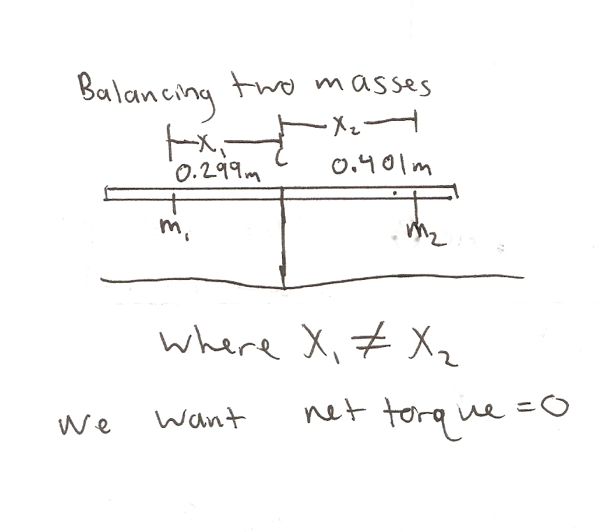 |
| Fig 3 |
Is it necessary to include the mass of the clamps in your calculations?
Yes! It is crucial as they are also applying their own separate weight force to the meter stick in addition to the known mass we have added. These masses are critical to know in order to calculate the net torque accurately.
The masses that were hung in the system were recorded, along with the mass of the clamps.
m1
= 0.15035 kg
m2
= 0.1098 kg
Calculate the net torque
Net Torque = T1 - T2 = 0
x1m1g
- x2m2g = 0
(0.299 m
)(0. 15035 kg)(9.8 m/s2) – (0.401 m)( 0.1098 kg)( 9.8 m/s2)
= 0
0.51-
0.51 = 0
This value matches entirely with the expected value of net torque
3) Now, a third mass of known value is added to the right of our meter stick. placing all the masses at different locations again, we once again search for the point where net torque = 0.
Pictured in fig 4 is the conceptual representation of the three masses at equilibrium.
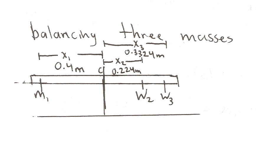 |
| fig 4 |
m1
= 0.15035 kg
m2
= 0.1098 kg
m3
= 0.1236 kg
Net Torque = T1 - T2 – T3 =
0
x1m1g
- x2m2g - x3m3g = 0
(0.4 m)(
0.15035 kg)( 9.8 m/s2) – (0.224 m)( 0.1098 kg)( 9.8 m/s2)
–(0.3224 m)( 0.1236 kg)( 9.8 m/s2) =0
0.59-
0.63= -0.04
The value of 0.04 was off from the expected value of 0 by 4%
4) In this step, mass one was replaced with a mass of unknown value. Pictured in fig 5 is how this step is performed.
 |
| fig 5 |
Calculate the unknown mass using the condition for rotational equilibrium.
m1
= unknown
m2
= 0.1098 kg
m3
= 0.1236 kg
Net Torque = T1 - T2 – T3 =
0
x1m1g
- x2m2g - x3m3g = 0
(0.407 m)(
m1)( 9.8 m/s2) – (0.224 m)( 0.1098 kg)( 9.8 m/s2)
–(0.3224 m)( 0.1236 kg)( 9.8 m/s2) =0
m1
= [(0.224 m)( 0.1098 kg)( 9.8 m/s2) +(0.3224 m)( 0.1236 kg)( 9.8 m/s2)]
/ [(0.407 m)(9.8 m/s2)]
m1
= 0.158 kg
Weighing the unknown mass on the scale, it was found to be 165.1 g or 0.1651 kg. Our calculated value differed from the measured value by the following:
[(165.1-158)/165.1]*100= 4.3% difference
5) In this step, only one mass of 200 g is hung at the 90 cm mark on the meter stick. Adjusting the position of the meter stick in its knife edge clamp, it is once again balanced. Calculate the mass of the stick.
Pictured in fig 6 is how the meter stick was balanced at a given point with a mass hanging from the 90 cm mark.
 |
| fig 6 |
m1
= 0.2167 kg
Net Torque = Tg - T1 = 0
xmmmg
- x1m1g = 0
0.282mmg
– 0.12*0.2167*g = 0
0.282mm
= 0.12*0.2167
mm
= 0.0922 kg
Should the mass of the clamp be included as part of the mass of the meter stick?
No, in this case it would only add further error to our calculations. The stick here is not affected by the clamp's mass, it is simply balancing about that point. Only the mass of the stick itself need to be taken into account in order to calculate the center of gravity's influence on torque.
Since the mass of the meter stick was found to be 0.0927 kg without the clamp, we calculate the difference.
[(0.927-0.0922)/0.0927]*100
= 0.65% difference
6) With the added mass still at the 90 cm mark, imagine that an additional 100 g is placed at the 30 cm mark on the meter stick. Calculate the position of the center of mass of this combination of masses and lever arm distances.
Pictured in fig 7 is how the center of gravity can be found using the net torque formula and a lot of algebra.
 |
| fig 7 |
Actually performing this experiment with the meter stick we were given, we found that the actual center of mass of the system was at the 61.1 cm mark. The percent difference is calculated as follows:
Percent difference = |(actual –
measured)/ actual|*100
|(61.1 – 60.8)/ 61.1|*100 = 0.5%
difference
Conclusion:
Upon completion of the lab, one obtained a better understanding of rotational torque and center of gravity. The points of equilibrium in rotational torque were able to be analyzed in multiple contexts. There were a few minor sources of error in this lab:
1) We may have miscalculated our actual center of gravity by a few millimeters.
2) The measurements of the lever arms of each weight may have been measured slightly wrong.
Overall, the measurements and calculations made in this lab seemed to be very accurate. The concept of rotational equilibrium was entirely supported by our tests.
No comments:
Post a Comment